

Matrix variable (array, curve, map)
Besides the scalar variable, QInsight also supports the Matrix variable type — a contiguous block of bytes interpreted as a table of values with optional axes. The typical use case is calibration data of control units: value blocks, characteristics, and maps (the ASAP2 types VAL_BLK, CURVE, and MAP).
Depending on which axes are defined, the variable takes one of three shapes:
| Shape | Axes | Data | Example |
|---|---|---|---|
| Array | none | N values | a block of 16 correction constants |
| Curve | X | 1×N values | a sensor characteristic (8 points) |
| Map | X + Y | N×M values | an ignition map speed × temperature |
The axes carry the breakpoints (the points where the map is defined), the data section carries the values themselves. The whole matrix — axes and data — is read from the device as one contiguous block (only the changed cells are written) and is displayed by the Matrix control.
Creating the variable
- Open Home → Project Configuration → Variables.
- In the drop-down next to the + button choose Matrix and click +.
- In the variable detail, fill in — besides the usual properties (Name, Label…) — the three matrix-specific fields: Default Data Type, Endianness, and Layout.

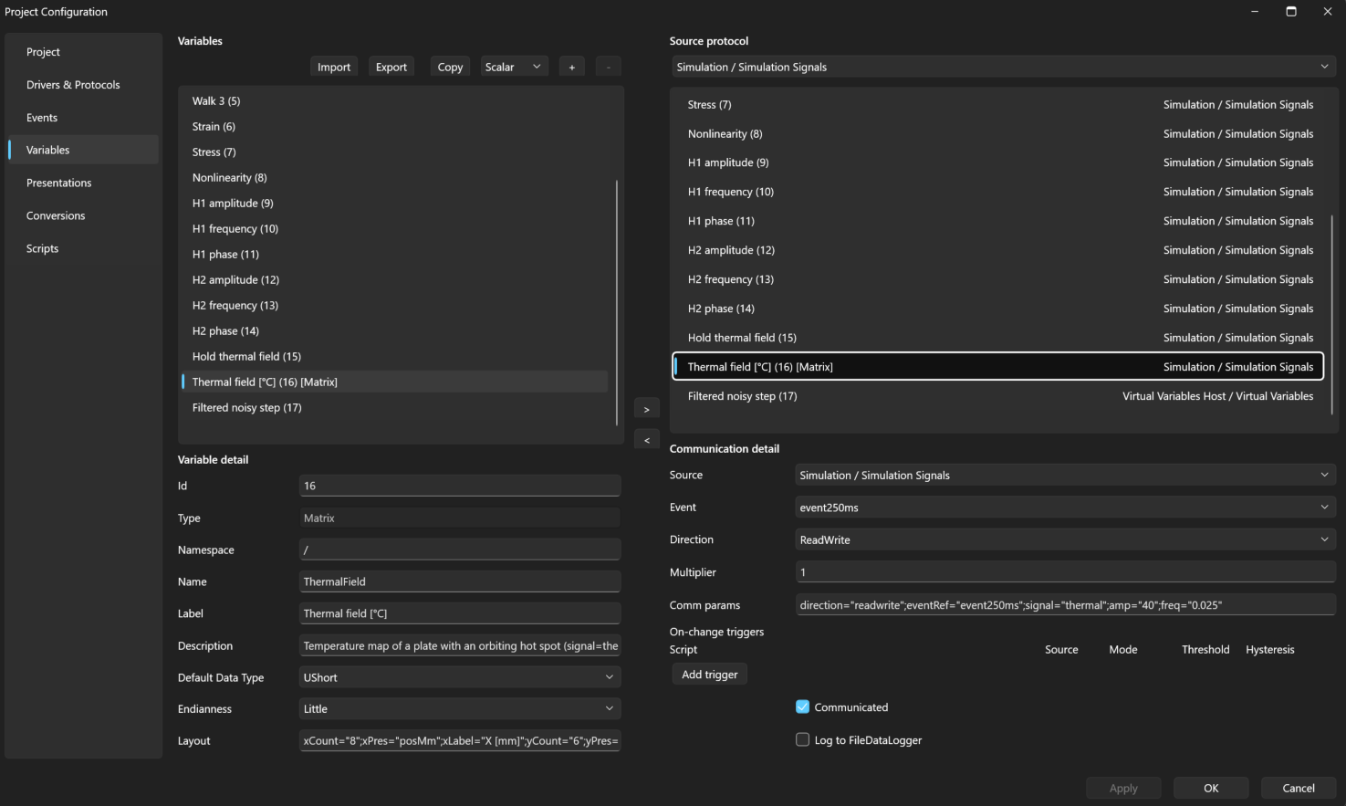
The screenshot shows the 8 × 6 thermal field from the
Simulation: all signals example: element
type UShort, little endian and the Layout
xCount="8";xPres="posMm";xLabel="X [mm]";yCount="6";yPres="posMm";yLabel="Y [mm]";dataPres="tempC"
Default Data Type and Endianness
- Default Data Type — the element type used by every section that
does not set its own type in the Layout. The default is
byte. - Endianness — the byte order of multi-byte elements (
Little/Big). It applies to the whole block, i.e. to the axes and the data.
Supported element types (the string type cannot be used in a matrix):
| Type | Element size |
|---|---|
byte, sbyte | 1 B |
ushort, short | 2 B |
uint, int, float | 4 B |
ulong, long, double | 8 B |
Layout — defining the sections
The Layout field describes the matrix sections with the same
key="value";… notation you know from the Settings and Comm params
fields. Sections are defined in numbers of values (not bytes) — byte
offsets and the total size are derived automatically from the counts and
element types.
| Key | Meaning |
|---|---|
xCount | number of X-axis breakpoints (columns); providing the key creates the X axis |
xType | element type of the X axis (otherwise Default Data Type) |
xPres | name of the presentation for the X axis |
xLabel | X-axis caption — the Matrix control shows it above the table |
yCount | number of Y-axis breakpoints (rows); requires the X axis |
yType, yPres, yLabel | the same for the Y axis (the caption is drawn vertically on the left) |
dataCount | number of data values — only for an array without axes |
dataType | element type of the data section (otherwise Default Data Type) |
dataPres | name of the presentation for the data |
Rules:
- An array (no axes) must specify
dataCount. With axes,dataCountis not given — the data count is derived:xCountfor a curve,xCount × yCountfor a map. - The Y axis requires the X axis (
yCountwithoutxCountis an error). xType/xPres/xLabelwithoutxCountis an error (same for Y).- Presentations (
xPres,yPres,dataPres) reference the project presentations by name — they must exist. The data section is captioned by the Label of the variable itself; there is no separatedataLabel. - An invalid Layout shows up immediately — the field gets a red border and the error is displayed as a tooltip.
Examples
Array — 16 values of type float (64 B):
dataCount="16";dataType="float"
Curve — 8 speed breakpoints and 8 torque values:
xCount="8";xPres="Speed";xLabel="Speed [RPM]";dataPres="Torque"
Map — 3 columns (speed) × 2 rows (temperature), with captions on both axes:
xCount="3";xPres="Speed";xLabel="Speed [RPM]";yCount="2";yPres="Temp";yLabel="Temp. [K]";dataPres="Torque"
Memory layout of the block
The block always has the order: X axis → Y axis → data; map data is
stored row-major (index = y × xCount + x). For the 3×2 map from the
example above with Default Data Type = ushort and no per-section types:
| Section | Values | Bytes (offset) |
|---|---|---|
| X axis | 3 | 0–5 |
| Y axis | 2 | 6–9 |
| data (2 rows × 3 columns) | 6 | 10–21 |
11 values = 22 B in total. If you change the type of a section (xType,
yType, dataType), the offsets are recomputed automatically.
Per-section presentation and conversion
Each section has its own presentation — axes usually have different units and scaling than the data (speed × temperature × torque). The same rules as for scalar variables apply:
- A linear conversion turns the raw value from the block into an
engineering value (
eng = raw × Multiplier + Offset); the presentation's Print Format and Unit define how it is shown. - An enum conversion shows the state name instead of the number.
- A section without a presentation shows the raw value directly.
When editing in write mode you always enter the engineering value — the raw value written to the device is obtained by the inverse conversion (rounded and range-checked against the element data type).
Size limits
The largest possible matrix depends on the protocol you assign it to:
| Protocol | Limit | Reason |
|---|---|---|
Modbus Master — direction="read" | 125 registers = 250 B (axes + data) | the whole matrix is read with a single FC03/FC04 request |
Modbus Master — write / readWrite | 123 registers = 246 B (axes + data) | Write Multiple Registers (FC16) carries at most 123 registers |
| XCP (on CAN and on TCP) | data section 16,384 B (64 × 64 × 4) + axes | block-mode transfer, see below |
The limit is checked by the protocol, not by the Project
Configuration editor — the editor accepts a matrix of any size (only the
Layout itself is validated). A matrix that does not fit its protocol's
limit is rejected by the protocol: the log shows the warning
Protocol variable specification for variable … could not be created (…)
with the reason (e.g. …exceeding the Modbus limit of 123 registers (246 bytes) per request. or …the XCP limit is 16384 bytes (64 × 64 × 4).)
and the variable is not communicated.
Assigning to a protocol
You assign a matrix to a protocol the same way as a scalar variable (the
arrow button into Communicated). Matrices are currently supported by
the Modbus Master and XCP (on CAN and on TCP); in the Simulation
Signals example the thermal signal generates one as well.
Modbus Master
For the Modbus Master, enter Comm params such as:
registerType="holdingRegister";address="100";direction="readWrite";eventRef="poll500ms"
Differences from a scalar variable:
- A matrix may only live in a register table (
holdingRegister, orinputRegisterfor reading) — the bit tablescoil/discreteInputare rejected by validation. - The block occupies a contiguous register range starting at
address; register count = size in bytes / 2 (rounded up). The example map (22 B) occupies registers 100–110. - The whole matrix is read with a single request FC03/FC04; writes send only the registers of the changed cells (FC06/FC16).
wordOrderdoes not apply to a matrix — the byte order is driven by the variable's Endianness. A Modbus register is 2 bytes, high byte first.
Tip: with
ushortcells andEndianness = Big, one cell maps exactly to one register and the values in QInsight match the device registers 1:1. Beware of the traps:bytecells pack two cells into one register, andushort+Littleswaps the bytes (5 becomes 1280).
XCP (on CAN, on TCP)
For XCP the Comm params keys are the same as for a scalar variable, e.g. the ignition map of the Nucleo H723 example:
address="0x24014270";addressExtension="0";direction="readWrite";multiplier="1";eventRef="OnRequest"
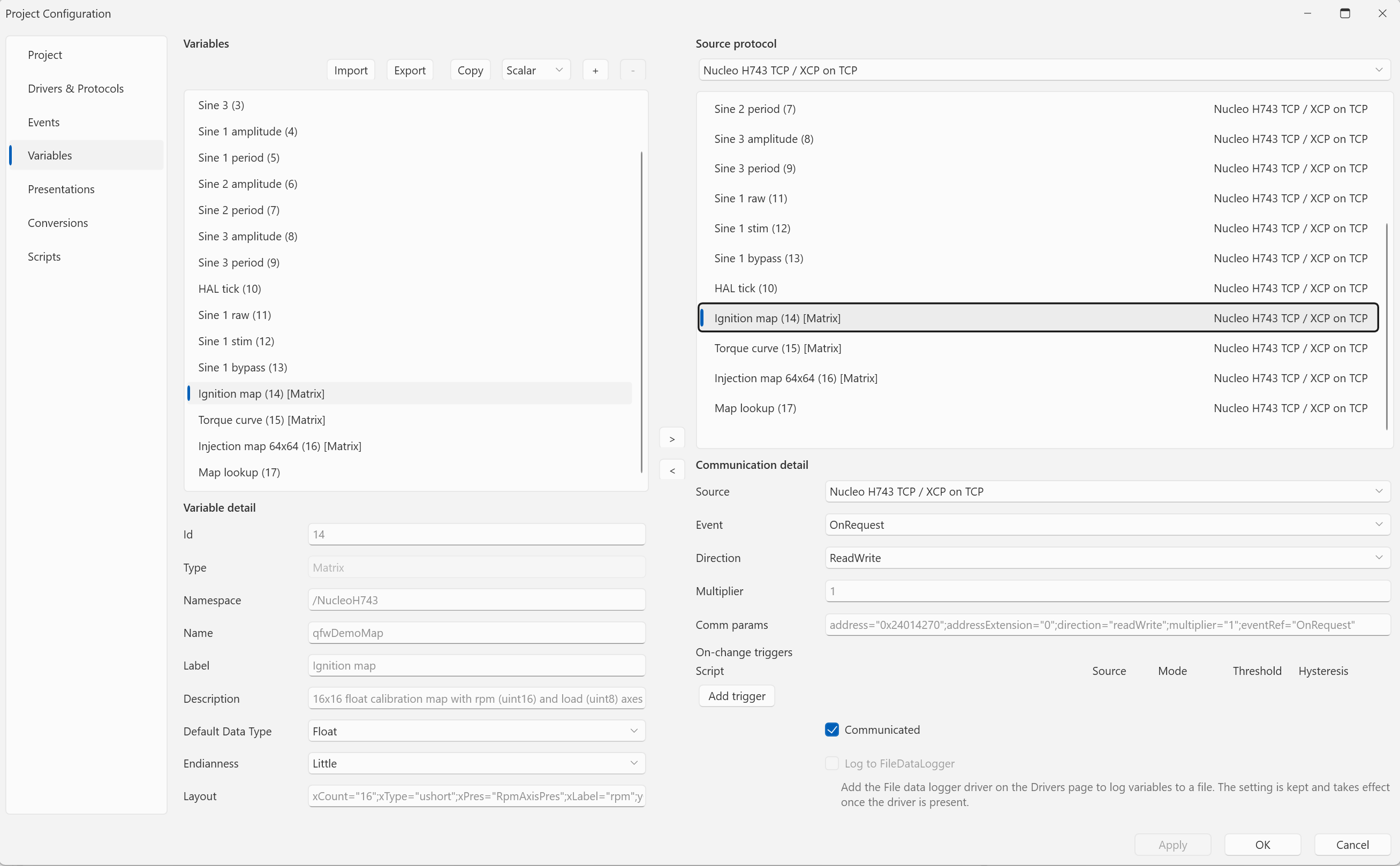
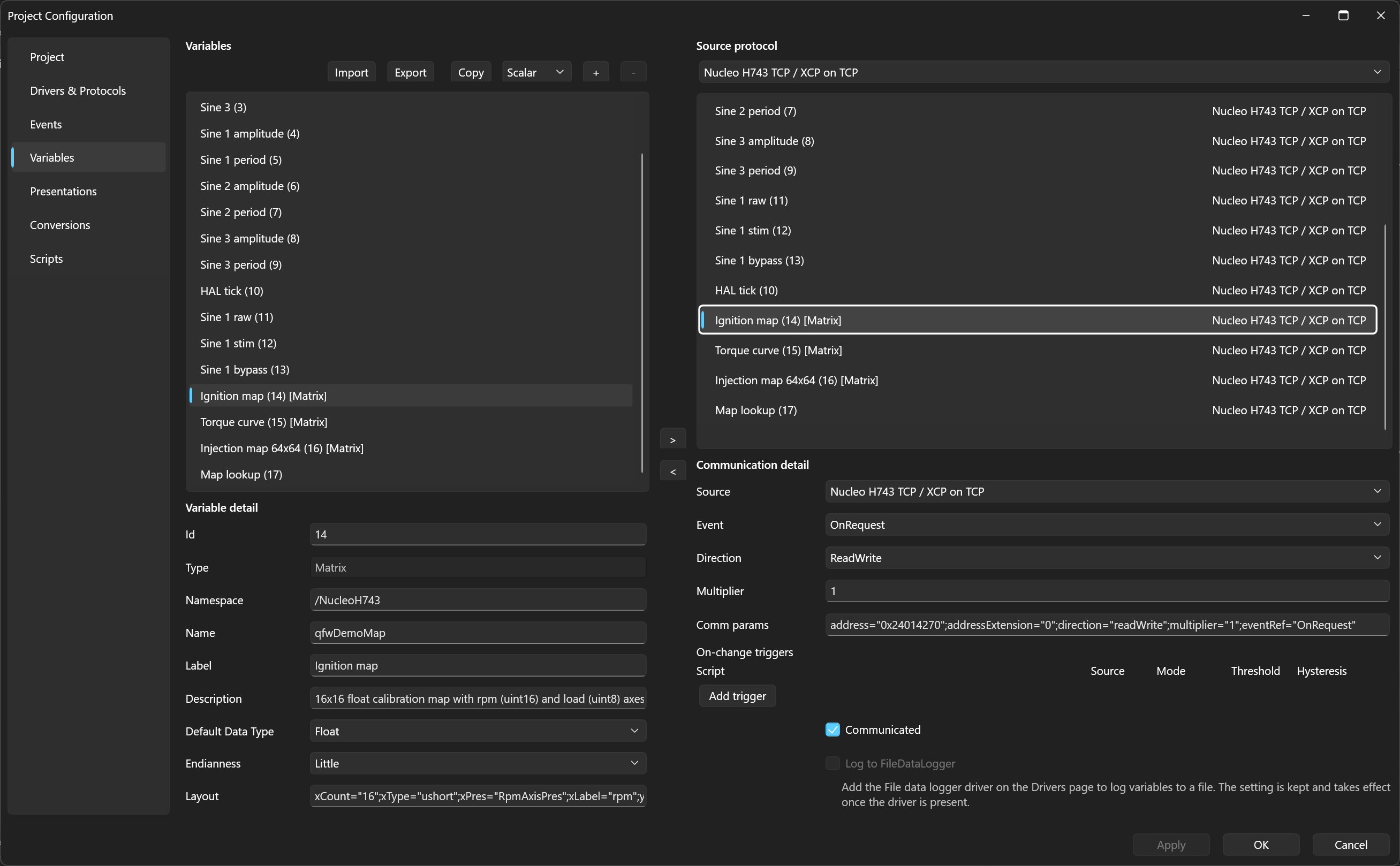
address(+addressExtension) is the start of the whole block, i.e. the first X-axis element (the start of the data for an array without axes). The section order in ECU memory must follow the memory layout of the block: X axis → Y axis → data row by row.- The optional
sizekey must equal the size of the whole block (axes + data), otherwise it is a configuration error.dataTypeis ignored for a matrix — the element types come from the Layout. - The variable's Endianness must match the ECU. The block travels raw and is decoded by the variable's Endianness; a mismatch with the ECU byte order is reported by a warning after connecting (the data is not changed).
- Event: periodic — the whole matrix is polled as one block every
period; On Request — the matrix is not polled and is read with the
Read button of the Matrix control.
A missing
eventRef(with a direction other thanwrite) is a configuration error. - A matrix cannot be bound to a DAQ/STIM event — the protocol rejects it with the error cannot bind to the DAQ/STIM event channel … a matrix is polled by a periodic event or read on request.
Block transfers. A block of up to MAX_CTO − 1 bytes (247 B on TCP,
7 B on CAN) is read with a single SHORT_UPLOAD. A larger block is read
with one SET_MTA and a series of UPLOADs of at most 255 B, which the
ECU answers in block mode with a burst of packets without further
requests. Writes use SET_MTA + DOWNLOAD/DOWNLOAD_NEXT in blocks
(with master block mode). If the ECU does not support block mode,
QInsight chains the transfer packet by packet — it works, only slower.
A multi-packet transfer is not atomic.
Cell writes. A write does not send the whole matrix: the edited cells are sorted by offset, neighbouring cells are merged into contiguous windows and each window is written separately. A pasted row of 64 cells is thus a single transfer.
As a rough guide: on TCP (loopback against the QFW SDK pc_server)
reading a 1,072 B map takes about 3.5 ms and a 64 × 64 map
(16,640 B) about 6 ms. On CAN (500 kbit/s) the times are orders of
magnitude longer.
Complete projects with maps, a curve and a 64 × 64 map are in the XCP on TCP — calibration maps and XCP on CAN — calibration maps examples.
Next
Display and edit the matrix with the Matrix control.